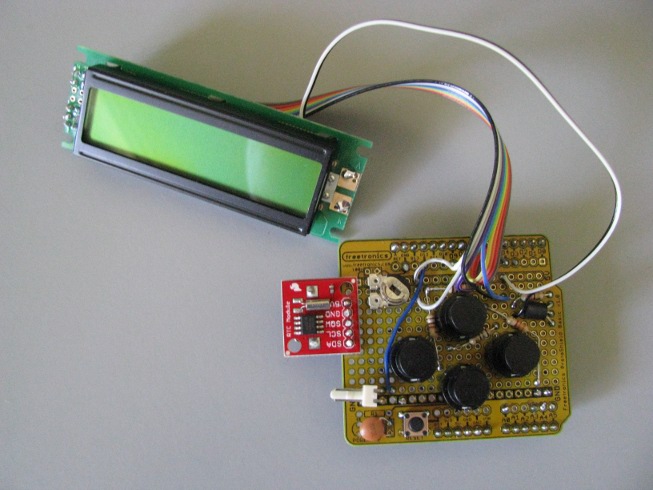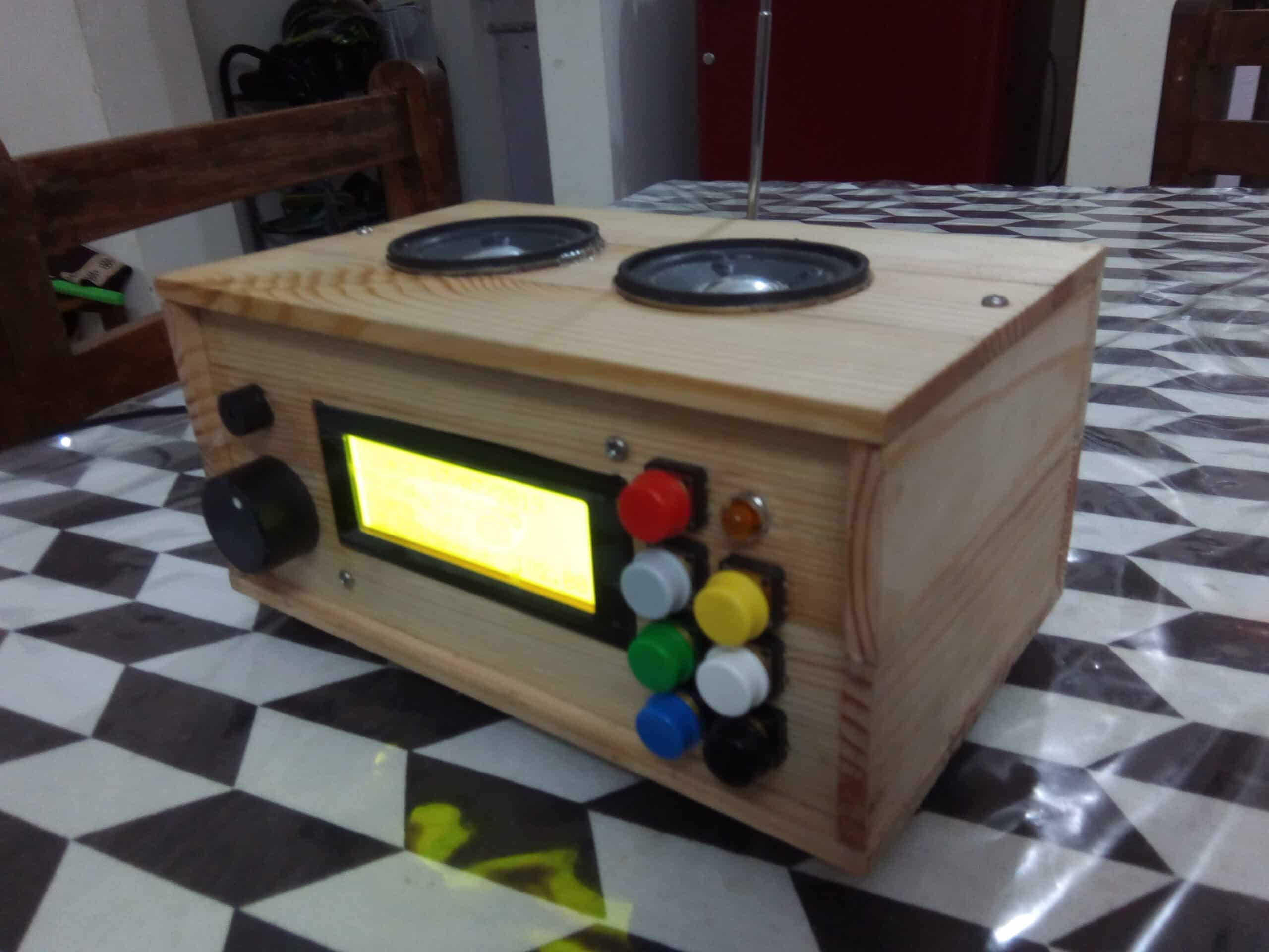
It’ll go to alarm mode and asks for hours with current time being displayed. In order to set the alarm, we press the set button. The code for Arduino is uploaded and the LCD displays the current date and time. The working of the project is explained below.Īll the connections are made as per the shown circuit diagram. The aim of this project is to create a real time clock along with an alarm feature.

A buzzer is connected to pin 11 of Arduino that acts as an alarm. These buttons are connected to pins 8, 9 and 10 of Arduino. RS, E, D4, D5, D6 and D7 (Pins 4, 6, 11, 12, 13 and 14) of LCD are connected to pins 2, 3, 4, 5, 6 and 7 of Arduino. 6 pins of LCD must be connected to Arduino. Both these pins of RTC are pulled high using 10KΩ resistors.Īn LCD is used to display the clock. These are connected to respective SDA and SCL pins of RTC. Analog pins 4 and 5 will act as SDA (Serial Data) and SCL (Serial Clock). There are two pins on Arduino for I2C communication. I2C protocol is a method of communication between a faster device (Microcontroller or Arduino in this case) in master mode and a slower device (RTC) in slave mode.


#Arduino radio clock serial
The communication between microcontroller and RTC IC DS1307 is serial I2C bidirectional bus. Aģ2.768 KHz crystal is connected to the oscillator terminal of DS1307 for 1 Hz oscillations. A 3V backup battery must be connected to the RTC so that the IC can automatically switch to the backup supply in case of power failure. The clock can operate in either 12 hour with AM/PM indication or 24 hour format. The clock function provides seconds, minutes and hours while the calendar function provides day, date, month and year values. DS1307 is the frequently used real time clock (RTC) IC for clock and calendar.


 0 kommentar(er)
